 |
Polarisation, P |
 |
Polarisation, P |
Polarisation, P
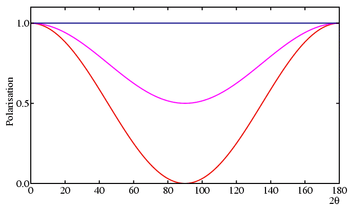
It is fairly obvious that the direction of polarisation of an X-ray photon can change as a result of scattering/diffraction. In fact there are two extreme cases to consider; when the change is maximal or when there is no change, depending on whether the initial polarisation is or is not in the plane containing the pre- and post-scattered X-rays:

In the first case, the component of polarisation resolved along the new (diffracted) direction is reduced by the cosine of the scattering angle (conventionally 2θ) and so the reduction in intensity would be by cos2 2θ (since intensity is proportional to the square of the amplitude). In the second case, the component of polarisation is clearly unaffected, and therefore unchanged, by the diffraction process so we would say, mathematically speaking, that the reduction factor is "1". These two extreme cases can in principle be realised by diffractometers on synchrotron sources due to the special polarised nature of the X-rays produced by synchrotron sources (see earlier section on Instrumentation: Synchrotron Sources and Methods). There is a third case, a mixture of the above two, which occurs with laboratory diffractometers since laboratory X-ray sources produce unpolarised X-rays, that is X-rays polarised equally in all possible directions; here the reduction factor will be the mean of the two previous extreme cases. We could summarise these three situations as follows:
| Case (1): Polarisation in plane of scattering, | P = cos2 2θ |
| Case (2): Polarisation perpendicular to plane of scattering, | P = 1 |
| Case (3): Unpolarised X-rays, | P = (1 + cos2 2θ )/2 |

There are some obvious conclusions from all of this:
Now lets look at our case problem again, the 200 and 111 reflections in NaCl. To calculate the effect of polarisation here we need some additional information: that the measurements are done on a laboratory powder diffractometer using copper Kα X-rays. Armed with this we will calculate the correction for the 111 case, and again for easy reference we will structure the model answer:
(1) Working out the angles θ, 2θ :
First we remind you how to calculate the d spacing in cubic crystals:
| dhkl = a/(h2 + k2 + l2 )1/2 |
| d111 = 5.638/(12 + 12 + 12 )1/2 = 5.638/√3 = 3.255 Å |
For Copper Kα radiation the wavelength is about 1.54 Å, and so inserting into Bragg's law gives us:
| 1.54 | = 2 × 3.255 × sin θ |
| sin θ | = 0.237 |
| θ | = sin−1(0.237) = 13.68° |
| 2θ | = 27.37° |
(2) Calculating P111 :
For the laboratory powder diffractometer we use the formula of Case (3):
| 2θ | = 27.37° |
| cos (2θ) | = 0.888 |
| cos2 (2θ) | = 0.789 |
| 1 + cos2 (2θ) | = 1.789 |
| P111 = (1 + cos2 (2θ ))/2 | = 0.894 |
So polarisation produces a reduction in intensity to 89% in the case of the 111 reflection. From the graphs, you should be able to see that it is reduced more for the 200 reflection, due to its smaller d spacing.
Polarisation & Monochromators
An unpolarized laboratory X-ray source diffracted by monochromator crystal produces a partially polarized X-ray beam. As for a diffracting sample, the degree of polarisation depends upon the diffraction angle, 2θM, of the monochromator. Assuming that the source, monochromator, sample, and detector are all in the same plane, then the polarisation factor in the presence of a monochromator is given by the expression:
Given that 2θM is small, the effect of the cos2 2θM in this expression is small as shown in the figure below, where the solid line is the polarisation factor without a monochromator and the dotted curve shows the polarisation correction with 2θM set to 28.44° (as for a Si<111> and Cu Kα1).

An alternative scenario is the case of a pre-sample monochromator on a powder diffraction synchrotron beamline. Here the incident beam is 100% plane polarized. Assuming that the monochromator and diffractometer all function in the vertical plane, then the polarisation remains unchanged from source to detector, so that no additional correction is required due to the monochromator.
|
© Copyright 1997-2006.
Birkbeck College, University of London.
|
Author(s):
Paul Barnes Jeremy Karl Cockcroft Simon Jacques Martin Vickers |