CONTENTS
1.1 On the origins of Moissanite
2.1 The existence of "polytypie" in SiC
3.1 Crystallography and structure
4.1 Early theories
5.1 General description of the ANNNI model
6.1 General methods
Summary
1 BACKGROUND
1.1 On the origins of Moissanite
Silicon carbide is even older than our solar system having wandered through the Milky Way for billions of years as stardust that was generated in the atmospheres of carbon rich red giant stars and from supernova remnants. The gravitational coalescence of our solar system trapped micron size silicon carbide grains in the meteorites that were forming from the accretion of the debris in clouds of interstellar gas.
Recent analysis of SiC grains found in the Murchison carbonaceous chondrite by Hoppe et al [1] has revealed that these starry messengers contain anomalous isotopic ratios of carbon and silicon. Clayton 1997 [2] and Timmes and Clayton 1996 [3] have discussed the galactic nature of these primitive pre-solar grains in terms of the ratios of 29Si/28Si and 30Si/28Si found in them. These are more abundant than in our sun indicating an origin from outside the solar system and closer to the galactic centre. Isotopic analysis of meteoritic silicon carbide pre-empts the information that may be recorded in the grains and is now offering a new and exciting tool for exploring the structure and evolution of our galaxy.
An iron meteorite from a terrestrial impact crater at Diablo Canyon in Arizona was chemically analysed by Henri Moissan originally in 1905 and found to contain hexagonal platelets of silicon carbide [4]. This was the first observation of the natural mineral Moissanite (SiC), although its synthetic preparation and properties had been earlier described by the same author in 1893 [5].
1.2 Initial manufacture of carborundum
Far from this heavenly scenario Eugene G Acheson had in fact already produced the first "artificial crystalline carbonaceous material" as a substitute for diamonds which he described in his 1892 resistance furnace patent [6]. He heated coke and silica together to make a substance that "may be designated under the general term Carborundum" describing the new compound "hitherto unknown to chemistry as represented by the formula SiC and that it may be known as silicide of carbon or carbide of silicon". This paved the way for the large-scale production of silicon carbide for the abrasives industry, and its main commercial use today. However the idea that a silicon-carbon bond might in fact exist was first proposed by the Swedish chemist Berzelius as early as 1824 [7].
A significant breakthrough in the manufacture of SiC arrived with the introduction of a new class of high temperature furnace described by Lely (1955) [8] for vapour growth of crystals. With the Lely type crystals fundamental studies on the electronic and lattice vibrational properties of SiC became possible. An example of a typical crystal grown by this method which was manufactured during the late 1960’s early 1970’s by the GEC Hirst Research Centre (UK) as part of its semiconductor research programme is shown in figure 1.
Figure 1. A photograph of a typical silicon carbide hexagonal platelet grown from the vapour by the modified Lely technique [8], used for research into semiconductor applications. The crystal dimensions are approximately 18 mm long across the page x 9-mm wide x 1.3-mm vertically at the right edge along which the polytypes are stacked (see also figure 5). The crystals are abrasive in nature and their colour has been linked to different polytypes by various authors (see section 4.1), the one pictured is black.
1.3 Potential semiconducting properties of SiC
A note published by H. J. Round in1907 [9] quietly heralded the technological potential usefulness of SiC as an electrical material in the 20th century. His observation of the curious phenomenon of a carborundum crystal giving out a yellowish light (always at the negative pole) during the passage of an electric current was the first made of a SiC light emitting diode (LED). He recorded the luminescence of other colours too notably blue, signalling its major technological advantage as a wide band gap semiconductor (see table 2. Bandgap energies of silicon carbide polytypes).
Recently Janzén et al. (1994) [10] have discussed the properties of SiC that make it a superior semiconductor to Si for high power, high temperature and high frequency device fabrication. The large bandgap allows high temperature operation (> 700 oC) with low current leakage. It has an extremely high thermal conductivity (5 W cm-1 K-1 c.f. diamond 9 W cm-1 K-1 which is a well known heat sink), and a high electric field breakdown strength (4 MV cm-1) which make it promising as a power transistor, thyristor or rectifier device. Because of its high saturated electron velocity (2.5 x 10 7cm s-1) it is also capable of generating large power at high frequencies proving useful as a microwave source for example in radar applications. Another important application is in the automobile industry where proximity of the electronic components to the engine is an advantage; the high chemical stability also enables sensors to work in a chemically aggressive high temperature environment. This potential has been known for some time but the poor quality of the material has handicapped device development, however epitaxial wafers of reasonably good quality SiC have now become available by Chemical Vapour Deposition (CVD) Kordina et al (1997) [11]. The major outstanding problem is the existence of micropipe defects in the commercially available
30 mm wafers (believed to be the hollow core of a screw dislocation with a huge Burger’s vector, several times the unit cell) preventing the exploitation of high current power devices Glass et al. (1997) [12].
2. INTRODUCTION
2.1 The existence of "polytypie" in SiC
Figure 2. A representation of the zig-zag chain structure of hexagonal SiC indicating the atomic positions (all atoms are in the 1120 plane). The stacking sequences of the common 2H, 4H and 6H polytypes in silicon carbide are shown, after Bechstedt et al (1997) [16]. The different 1100 planes within the hexagonal unit cells are denoted by A, B, C. The cubic (c) or hexagonal (h) character of Si-C bilayers in 0001 direction is given according to the parallel (c) or antiparallel (h) limiting bonds.
The study of polytypism in crystals began nearly 90 years ago when the word "polytypie" was first used by Baumhauer (1912) [13] in an attempt to describe materials that crystallize structurally into modifications that differ only along one crystallographic direction. From optical studies he discovered two new crystal structures of silicon carbide in addition to the commonly known 6-layered hexagonal type, differing in their stacking along the c axis.
Their existence was later confirmed by X-ray diffraction, Baumhauer (1915) [14]. These observations by themselves however did not attract widespread attention until morphological and structural studies in the 1940’s and 1950’s revealed several more new polytypes of SiC.
Schneer (1955) [15] called it "polymorphism in one dimension" in order to emphasise that two dimensions of the unit cells of different polytypes are identical whilst the third is a variable integral multiple of a common unit. The polytypic structures thus built up may be considered as stacked layers with repeat sequences ranging from 2 layers to many hundreds of layers; (see Fig. 2) in the extreme case of no finite repeat the polytype can be termed a one-dimensionally disordered layer. The most common polytypes of a given compound have short period stacking sequences e.g. in ZnS the principal structures are those of zinc-blende (….ABCABC…) and wurtzite (….ABAB…) the cubic and hexagonal forms respectively.
2.2 A brief review of the phenomenon
Several prominent theories have been put forward to explain the phenomenon; notably the first explanation based on definite principles of crystal building by Frank (1949) [17] the screw dislocation theory and soon after by Burton, Cabrera & Frank, (1951) [18]. Later derivatives of the theory were proposed by Mitchell (1957) [19] and Krishna & Verma (1965) [20]. The faulted matrix model due to Pandey & Krishna (1975 a, b, 1978) [21, 22], and the one-dimensional disorder theory of Jagodzinski (1954 a, b) [23] are amongst them. These are dealt with in more detail in section 4.1 and are mapped in table 4 theories of polytypism. An exhaustive description of polytypism in crystals is given in the review articles by Verma and Krishna (1966) [24], Trigunayat and Chadha (1971) [25] and Pandy & Krishna (1983) [26] summarising the status of understanding of the origin and growth of polytype structures. Schaffer in 1969 [27] listed the then known polytypes and their discoverers meanwhile the most recent survey of the phenomenon of polytypism in crystals was made by Trigunayat (1991) [28].
2.3 Physical factors affecting the growth of silicon carbide
The influence of temperature on polytype formation was considered by Ramsdell and Khon (1952) [29] who suggested that accretion of clusters of atoms or "polymers" such as <33>, <32> (see section 3.2 on polytype notations) might occur in a given temperature range and account for the structure series observed. They postulated that since 2H <11> (for polytype stacking see figure 1) is not found in the series it was unlikely that the crystal is built from the vapour phase by monolayer addition. They argued that accretion of the "units" would result in the formation of "pure" types like 6H <33>, 15R <32 or 23>3, 4H <22>, 21R <34 or 43>3 and 8H <44>, the coexistence of polymers in various temperature ranges would result in mixed polytypes. The presence of a random disorder of layers often observed in SiC was attributed to the fluctuating conditions in the furnace, the authors stated that the theory was put forward on purely theoretical grounds and that the polymers were hypothetical.
Knippenburg (1963) [30] obtained the relationship between structure and temperature of occurrence of polytypes shown in figure 3 suggesting that b -SiC was the metastable form while a -SiC 2H was the stable low temperature form. Meanwhile Pandey and Krishna (1983) [26] noted that there is experimental evidence to suggest solid state transformations produced by the thermal annealing of 2H Þ 3C crystals between 1400 0C to 1600 0C. Also observations of a 2H Þ 6H transformation commencing above 1600 0C point to the view that 2H is the metastable modification while the cubic form is stable at low temperatures. Several workers have reported various findings on the role of impurity content on polytype stability, notably Hayashi (1960) [31], Knippenburg [30] and Loubser et al (1969) [32]. In general the incorporation of impurities tended to increase the disorder phenomenon found in the crystals.
Figure 3. Graph of the stability regime of the various polytypes as a function of temperature after Knippenburg [30]. Several forms exist at temperatures above 2000 oC. Solid state transformations have been observed in silicon carbide by several authors.
2.4 Why is SiC so exceptional ?
The free energy of a structure is given by the Gibbs function:
G = U – T S + P V 2.1
Where U is the internal energy, T the thermodynamic temperature, S the entropy of the system and P, V the state variables pressure and volume of the substance under consideration. As can be seen from figure 3 SiC is synthesized at very high temperatures so small changes in entropy S affect the free energy considerably. Now as the internal energy for various polytypes is negligible (D U = 0) and they all have the same density (V = m / r ) the polytype that has the maximum entropy has the minimum free energy under any conditions of temperature and pressure. This implies that a completely disordered arrangement of atoms along the c-axis is thermodynamically the most stable. Thus the existence of polytypes appears anomalous, some long period polytypes seem to require ordering forces with a range much larger than the atomic forces involving a co-operation of short range forces to produce long range order. Whether the cause of this is the vibration entropy of the structure or the result of growth mechanisms from screw dislocations is still an open question. The intriguing behaviour of this unique material still fascinates research into the rich variety of the polytypism it exhibits.
3. A DESCRIPTION OF SILICON CARBIDE
3.1 Crystallography and structure
This section will present some of the main facts and figures for reference detailing the physical properties of silicon carbide. The purpose is to provide a nomenclature for the description of polytypic structures.
The hexagonal unit cell of the predominant 6H polytype of SiC has the crystallographic dimensions a = b = 3.078 Å (which is common to all hexagonal polytypes) while c is a variable integral multiple of 2.518 Å (the SiC – SiC layer spacing, see figure 4). Details of the refinement of the crystal structure of the 6H polytype are given by Gomes de Mesquita (1967) [33] while the original structure determination was undertaken by Ott (1925 a, b) [34]. The space group symmetry of SiC can be summarised as follows, after Verma and Krishna [24]:
P3m1 - Trigonal (Hexagonal odd number of layers)
P63mc - Hexagonal (Hex even no. layers)
R3m - Trigonal (Rhombohedral polytypes)
Figure 4. An atomic model of the 6H polytype of SiC looking along the 1120 direction constructed using molecular simulation software, after the structure refinement by Gomes de Mesquita A. H. (1967) [33]. The unit cell is shown by the broken lines and has a c-axis dimension of 15.108 Å along the z direction from the stacking sequence ABCACB as shown in table 1. SiC is essentially a covalently bonded material with a spacing of 2.518 Å between the layers, the Si-C (orange-grey) bond length is 1. 888 Å
3.2 The notations used to describe polytypes
The different polytypes of SiC were first called Types I, II, III etc. in the order of their discovery (15R, 6H, 4H) but as more were found it was realised a suitable nomenclature had to be devised. Various notations to describe the different polytypes have been developed over the years and these are listed in table 1. The notation used throughout is after Ramsdell (1947) [35] unless convenience dictates otherwise.
|
Jagodzinski |
Ramsdell |
Hägg |
Zhdanov |
Stacking Sequence |
|
khkh |
4H |
++-- |
22 |
ABAC |
|
hkkhkk |
6H |
+++--- |
33 |
ABCACB |
|
(kkhkh)3 |
15R |
(++---)3 |
(23)3 |
ABCBACABACBCACB |
Table 1. The various notations used to classify polytypes and as applied to the three most common types. The h, k notation used by Jagodzinski describes alternative successive rotations of zero and 180 degrees respectively of one layer with respect to its neighbour; the Ramsdell notation signifies the c-axis repeat and lattice type (H-Hexagonal, R-Rhombohedral); Hägg counts as + the moves A-B, B-C, C-A and as - the moves A-C, C-B, B-A and lists the consecutive + or - signs; while Zhdanov sums the number of like signs used in the previous notation.
Three other common notations due to Hägg (1943) [36], Zhdanov (1945,1946) [37, 38] and Jagodzinski (1949) [39] have all been used to denote the fully descriptive but cumbersome layer (ABC) stacking sequences and are discussed more fully by Verma and Krishna [24].
A brief description of their use now follows with attention being paid to the use of the Zhdanov symbols as this is frequently used in descriptions using the ANNNI model (see section 5). It is a well known classical device to describe three-dimensional close packed crystal structures through arrangements of two-dimensional layers with each sphere in a layer in contact with six others around it and no two successive layers alike. One of two possible stacking sequences then follows: the hexagonal close packing (hpc) ABABABAB…. etc or the face centered cubic (fcc) ABCABCABC…… etc arrangements. The spatial location of the atoms in the unit cell can be easily worked out from the knowledge of the ABC sequence, which is characteristic of a given polytype. In this way the ABC notation affords a complete and unambiguous representation but does not reveal the crystal symmetry, and is inconveniently large for high polytypes. The Ramsdell notation is particularly compact identifying the polytype as a number signifying the layer repeat in the unit cell followed by a letter describing the lattice type, however it fails to disclose the relationship between the layers. The remaining systems make use of the relative position of neighbouring atomic layers. The three orientations can be converted into the other either by a translation of +/- (1/3, 2/3) or a rotation of 60o in its own plane. The conversions can be arranged into two categories as cyclic (A ® B ® C) and anticyclic (A ® C ® B) and can be visualised through translation as done by Hägg using the symbols + and – respectively. The sequence of the symbols in the unit cell then represents the polytype (see table 2 above).

Figure 5. Schematic of the layering of polytypes along the crystal c-axis in vapour grown SiC platelets (as photographed in figure1). The crystals form in hexagonal platelets varying in thickness from about 100 m m up to approximately 3 mm containing various polytype combinations in coalescence. One-dimensional disorder can be found between the polytypes and stacking faults also occur along this axis.
The Nabarro-Frank (1951) [41] operators D and Ñ adopted for rotation can be used in the same way providing compactness for Rhombohedral polytypes in which the same sequence repeats three times in the unit cell e.g. 15R can be written (++---)3 or (D D Ñ Ñ Ñ )3.When successive symbols of one kind are added and expressed as numerals the notation becomes powerful in expressing long polytypes and representing the zig-zag sequences of the atoms at once. This notation was devised by Zhdanov and has been used by many authors especially when considering the binary nature of adjacent layers.
A system of notation taking into account the relative positions of layers in the immediate neighbourhood of a particular layer on both sides has been used by Jagodzinski [39]. If a layer has similar layers situated on its sides e.g. BCB it is designated "h", if the orientations are different e.g. ACB then it is denoted "c". The symbols derive from the hcp (ABAB…) and cubic close packing (ABCABC…) of layers described above (see fig. 2), Jagodzinski employs the symbols h, k instead of h and c (see table 1).
3.3 Bandgap energies and data on SiC
Lately synthetic Moissanite has been available as a gemstone to rival diamond from which it is barely distinguishable in terms of its physical properties some of which are summarised in table 2. Variations in the bandgap energies of the various polytypes have been calculated using an interface matching technique of electronic wave functions by Van Haeringen et al. (1977) [40]. The corresponding wavelengths l (nm) were calculated from these energies (eV)
![]() using the Planck and De Broglie expressions:
using the Planck and De Broglie expressions:
Where h = 6.6 x 10⁻³⁴ Js, e = 1.6 x 10⁻¹⁹ C, c = 3x 10⁸ m s-1.
|
Hardness |
Refractive index |
Thermal conductivity |
Density |
|
(Mhos) |
(W cm-1 K-1) |
g cm-3 |
|
|
9.25 |
2.64 |
4.9 |
3.217 |
|
Polytype |
3C |
15R |
6H |
4H |
2H |
|
Bandgap(eV)* |
2.40 |
3.03 |
3.05 |
3.34 |
4.04 |
|
l (nm) |
515.6 |
408.4 |
405.7 |
370.5 |
306.3 |
Table 2. Some physical properties of silicon carbide. Variations in the bandgap energies in SiC have been calculated by Van Haeringen et al. [40]. The corresponding values for the optical wavelengths were calculated using l = h c / e V for comparison the standard Hblue = 434 nm.
4. ON THE ORIGINS OF POLYTYPISM
4.1 Early Theories
As early as 1912 Baumhauer [13] tried to correlate the occurrence of various polytypes in SiC crystals with their colour: Hayashi [31] summarised that green crystals were characteristic of the 6H polytype, yellow of 15R and dark black of 4H.
Screw dislocation theory:
Frank (1949), Burton, Cabrera & Frank (1951)
Frank [17, 41] directly extended the screw dislocation theory of crystal growth, Burton et al. [18], to explain the formation of SiC polytypes in thin crystal platelets at low supersaturation. He suggested that the existence of dislocations on a crystal face exposes a molecular terrace and the need for fresh two dimensional nucleation never arises, instead the face can grow perpetually "up a spiral staircase". The origin of these ledges on the surface caused by screw dislocations was made possible by a "buckle followed by slip" mechanism as the platelet became heavily stressed through the non-uniform distribution of impurities or thermal stresses. The resulting structure that is formed is then repeated with a period equal to the pitch of the screw i.e. the Burger’s vector of the dislocation. If this slip vector is an integral multiple of the unit cell height then the original structure continues to grow, otherwise a different polytype with cell dimensions equal to the step height results. Screw dislocations of different Burgers vectors may thus create different polytypes.
This theory has acquired experimental support with the observation of growth spirals by Amelinckx (1951) [42, 44] which have been confirmed by Verma (1951) [43, 45]. Using phase contrast microscopy and multiple beam interferometry he measured the step height of type II (6H) as 15.1 Å (c.f. structure determination by Ref [33] fig. 4). However it is not easily reconciled with the observation of polytype coalescence and has several other shortcomings which are summarised below:
Frank’s screw dislocation theory has been fully discussed by Verma and Krishna [24].
Structure series:
Mitchell (1957), Krishna & Verma (1965)
Mitchell [19] proposed a correlation between theoretical screw dislocations and the known polytypes of silicon carbide producing a structural series created on the basic 6H <33>, 4H <22> and 15R <23>3 polytypes. By displacing the zig-zag chains of atoms to form gaps in the 1120 plane caused by screw dislocations he was able to identify some gaps that were unstable and the resulting structures were not expected. He was thus able to formulate a list of all the theoretically possible structures that could form although no reason was given for creation of the basic structure in the initial platelet and its surface layers. He summarises that dislocations in one phase may generate structures identical to those of a second basic phase. Type 6H may generate 15R, type 15R may generate 4H, type 15R may generate both types 6H and 4H perhaps accounting for the common syntactic coalescence of silicon carbide forms. If simple dislocations were the only factor involved he concludes it would be unlikely for 6H and 4H to coexist without the presence of some 15R, an interesting thought.
Krishna and Verma [20] corrected the assumptions for the deduction of possible polytypes after Mitchell and a simplified version of their structure series is shown in table 3. In particular they point out
|
Series |
known polytypes |
|
(33)n 32 |
15R, 33R, 51R, 87R, 105R, 141R, 393R |
|
(33)n 34 |
21R, 39R, 57R, 111R |
|
(22)n 23 |
15R, 27R, 51R |
|
(22)n 25 |
None |
|
(23)n 32 |
15R, 10H |
|
(23)n 33 |
6H, 33R |
|
(23)n 24 |
None |
|
(23)n 22 |
4H, 19R |
|
(23)n 27 |
None |
Table 3. Structure series after Krishna and Verma [20]. It is interesting to note that many polytypes are based on bands of <2> and <3> in combination as remarked by Trigunayat & Chadha [25].
Faulted matrix model:
Pandey & Krishna (1975 a, b, 1978)
The faulted matrix model proposed by Pandey and Krishna [21, 22] considered all polytypes to be some variation on a basic structure (4H, 6H and 15R) generated by stacking faults and as such represents the synthesis of improvements to the dislocation model.
One-dimensional disorder theory:
Jagodzinski (1954 a, b)
Jagodzinski [23] developed thermodynamic arguments to account for the existence of polytype behaviour guided by the observed structure-temperature relationship for SiC polytypes and the characteristic abundance of one-dimensional disorder displayed by the crystals. The disorder arises from the presence of random stacking faults in the layers e.g. an A layer found in place of a B layer manifest as diffuse streaking along the diffraction rows in x-ray photographs (see fig. 8). He argued that edge dislocations could be created with greater ease than screw dislocations requiring less energy for their formation and resulting in stacking faults by layer displacement.
He objected to the dislocation theory pointing out that such growth should be completely ordered whereas it is not and that it should also result in needle shaped crystals rather than platelets along the(0001) direction as observed. He suggested that the entropy of a structure would consist of two parts (a) the configurational due to the relative positions of the atoms and (b) the vibrational entropy due to due movement of the atoms about their mean positions. He also defined a fault order degree:
a = nh / nh + nC. 4.1
Where nh = no.of hexagonal faulted layers and nc = no.of cubic faulted layers so the expression returns a value of 0 for a completely ordered structure. The Helmholtz free energy F of a polytype structure can be written as:
F = U - T S 4.2
Now the internal energy U (which can be written in terms of the potential energy and the vibrational energy of the system) and entropy S (which is composed of a configurational Sconf and vibrational Svib component) are functions of the disorder parameter a . Qualitative arguments result in the curves shown in figure 6 where an adjustment of a with respect to the nearest ordered type rather than cubic structure as first assumed yields the solid line for the configurational entropy rather than the dotted line. The vibrational component of the entropy decreases with increasing disorder but also significantly plays a greater role in one-dimensional disorder because the configurational entropy must be smaller than in the two or three-dimensional case.
Overall it can be seen that there are two maxima to the total entropy one at a = 0 (a completely ordered structure) and the other at a value of about 0.12, thermodynamically this implies that ordered and disordered structures in coexistence can be interpreted as metastable equilibrium. The implication from the graph is that the formation of completely ordered structures with larger periodicities is increasing improbable, i.e. more random disorder is
expected and this poses a problem with the theory because of the reported existence of well ordered long period polytypes. The question of the contribution of the vibrational energy differences between the various polytypes and its role in the stability of polytype formation is a topic that has received a lot of attention lately.
Figure 6. Variations of the configurational entropy Sconf vibration entropy Svib and total entropy S = Sconf + Svib as functions of the fault-order degree (a ) as envisaged by Jagodzinski (1954) [23].
Yet despite another model, the periodic slip process occurring after crystal growth has been completed, due to Mardix et al (1968) [46] no single theory has been so far able to fully account for the presence of all known polytypes. The obvious difficulty in characterising polytypes of a given compound is their commonly found large unit cells and the enormous number of possible stacking sequences for a given period.
Theories of Polytypism
|
Thermodynamic Separate Phases |
Û |
Growth Kinetic Mechanisms |
|
Equilibrium theories in general assume some polytypes exist as stable thermodynamic phases |
Non equilibrium kinetically dominated process (Dislocations, impurity atoms) |
|
|
"Disorder Phenomena & its relationship in the SiC polytypes" translation Jagodzinski (1954) |
"The growth of Carborundum: dislocations & Polytypism" Frank (1951) |
|
|
Axial Next Nearest Neighbour Ising model ANNNI Price & Yeomans (1984) |
A Faulted matrix model Pandey & Krishna Periodic slip process Mardix et al |
Table 4. The main theories of polytypism discussed in this section are mapped onto the underlying principle of their formation either in equilibrium or non-equilibrium using thermodynamics or dislocations as the driving force.
4.2 Modern Status
Bogdan and Alexander (1989 a, b) [47] have discussed computer algorithm techniques for generating layer sequences of polytypes and simulated random stacking faults in close packed structures. Monte Carlo computer simulations using different mechanisms for layer rearrangement with periodicities extending to 12 layers have been discussed by Ramasesha and Rao (1977) [48], while Ramasesha (1984) [49] discusses a competing interaction model in terms of the large number of known polytypes and one dimensional disorder based on the Ising spin model (see sections 4.3 and 5). The nearest neighbour interaction in this model is ferromagnetic while the next nearest neighbour is antiferromagnetic, the whole system is considered anisotropically. The Monte Carlo method has also been used by Kabra and Pandey (1989) [50] to simulate the 2H to 6H transformation above 1600 oC where stacking faults are introduced in a random space and time sequence. While recently Farkas-Jahnke (1994) [51] has used the novel approach of using Fibonnaci chains to generate the layer sequences frequently found in faulted ZnS polytypes.
A simpler method devised by Inoue (1982) [52] has produced 20 layer sequences of SiC polytypes by considering the Zhdanov symbol notation. Computer simulations have also been used by Goodby et al (1990) [53] in determining the energies of ZnS and SiC polytypes. Cheng et al (1988) [54] have used ab initio pseudo potential techniques to calculate the energies of SiC polytypes while yet further work by these authors (Cheng, Needs et al 1989) [55] on determining the Hamiltonian of an Ising spin array have concentrated on an inter layer interaction model. According to their work they find that the observed polytypes of SiC are roughly 0.01 eV per pair of SiC atoms lower in energy than the polytypes that are not seen in experiments.
A superlattice model of polytype formation with different degrees of disorder has recently been formulated by Kozielski and Tomaszewicz (1993) [56] based on Zn1-xCdxS while work on Order-Disorder (O-D) structures to include MDO (Maximum Degree of Order) polytypes has been discussed by Durovic (1993) [57]. Previously Zvyagin (1988) [58] has considered the relationships of polytype structures to hybrid (both commensurate & incommensurate), Order-Disorder (O-D) and modulated structures in attempting to describe the structural aspects of polytypism. More recently Zvyagin (1993) [59] has summarised the modern status of polytypism with emphasis on the nomenclature and the significance of the structural units (SU) used to describe it.
The foregoing attempts at explaining polytypism have relied upon layer sequencing methods with little regard to experimental observation of polytypes from bulk, thin film or surface measurements.
4.3 Recent ideas
Much attention has recently been focussed by a number of authors on using the ANNNI model which is described in greater detail in section 5 in attempting to explain polytypic behaviour. The application of an Axial Next-Nearest Neighbour Ising (ANNNI) model was proposed by Price and Yeomans (1984) [60] and described by Smith, Yeomans and Heine (1984) [61] as a mechanism for producing a large number of stable structures and polytypes with very long ranged periodicities. Yeomans and Price (1986) [62] have extended the Axial Ising model to include interactions up to third neighbours while Price and Yeomans (1988) [63] have reviewed the theoretical work on model systems.
5 Axial Next-Nearest Neighbour Ising Model (ANNNI)
5.1. General description of the ANNNI model
The Ising Model, Ising 1924 [64], is a well-known tool in statistical mechanics used to describe ferromagnetism and predict phase transitions and critical phenomena. It is based on a pair of discrete spin variables that can have one of two possible states that co-operate at low temperature to produce order and a large magnetisation and disorder and random alignment at high temperature. The model tries to imitate behaviour in which individual elements modify their behaviour so as to conform to the behaviour of other elements in their vicinity in its simplest form the interactions among the spin vectors is restricted to nearest neighbours.
Price and Yeomans (1984) [60] to describe polytypic behaviour in the case of the spinel structure and silicon carbide have used the Axial Next-Nearest Neighbour Ising (ANNNI) model. In this model the authors consider a basic structural unit to exist in one of two states conveniently labelled or ¯ . They propose the following requirements for a structure:
They consider layers perpendicular to the [010] direction in the b phase of a spinel structure. The ground state of each of these layers is ferromagnetic along the [001] direction and antiferromagnetic along [100] and can be described by a term in the
Hamiltonian:
![]() 5.1
5.1
Where the interaction parameters J0, J0’ > 0, and S nn denotes a sum over nearest-neighbour sites in the direction specified. As the temperature is raised the probability that the spins may flip is determined by exp (-2 J0 / kBT) where kB is Boltzmann’s constant and T is the thermodynamic temperature, in general J0 > > kBT and the layers themselves do not deviate from the ground state.
They now turn their attention to the nearest-neighbour (J1) interaction energy between layers, along the direction of stacking in this case the Hamiltonian may be written as:
![]() 5.2
5.2
At T = 0, 2J1 is the difference in energy between a ferromagnetic ( ) and an antiferromagnetic ( ¯ ) alignment of two neighbouring spins. Since both configurations occur frequently in observed spinel structures J1 can be considered to be small. A second next nearest-neighbour interaction (J2) in the stacking direction can then also be included in the Hamiltonian:
![]() 5.3
5.3
All of the above suggest that the stacking sequences observed in the spinel structures can be modelled by a Hamiltonian that takes into account both nearest and next nearest neighbours:
![]()
![]() 5.4
5.4
This ANNNI model was first introduced by Elliot (1961) [65] to describe the magnetic ordering in the heavy rare-earth metals and has received considerable attention lately.
5.2 The ANNNI model phase diagram
The resulting phase diagram includes many long-wavelength phases, which can be interpreted for our purposes as polytypes. Since the ordering within the layers is invariant it is only necessary to consider the ordering in the stacking direction. In this direction a typical phase will comprise a repeating sequence of up and down spins, for example:
… ¯ ¯ ¯ ¯ ¯ ¯ ¯ ¯ ¯ ¯ …
Consecutive spins of the same sign are termed bands, in the above example there are 3 bands of 2 spins followed by 1 three-band, this can be written <2223>. Generally < n1 n2 … nm > can be used which is analogous to the Zhdanov notation used in the description of polytypic materials.
In the first instance consider the ground state (T= 0) phase diagram of the ANNNI model which is shown in Figure 6. For J2 > 0 (ferromagnetic second neighbour bonds) the ground state is ferromagnetic (… …. or < ∞ >) for J1 > 0 and antiferromagnetic (… ¯ ¯ ¯ …. or < 1 >) for J1 < 0.
Figure 6. The phase diagram of the ANNNI model as described by equation 5.4. When the layers of spins +1 and –1 alternate one obtains an antiferromagnetic phase <1> and if all the layers have like spins one gets a ferromagnetic phase < ∞>.
5.3 A model for polytypic behaviour
The authors attempt to interpret the behaviour of polytypic materials in terms of this model, identifying each phase in the ANNNI with a polytypic structure. They do this by equating the symbols introduced above to describe the sequence of spin bands to the Zhdanov [37,38] notation structural units. The energy of interaction between the basic structural units is then represented by the spin interactions J0, J1 and J2. Stable polytypes will then correspond to the spin phase with minimum free energy and can be determined from the phase diagram. Transformations between polytypes occur because the effective interaction energies J1 and J2 vary as a function of pressure and temperature, by using this approach the conditions through which a polytype is subjected may be explained. The model provides insight to reversible behaviour, the frequent existence of short stacking sequences and the limited set of stable polytypes of a given compound.
6. METHODS TO STUDY POLYTYPES
6.1 General Methods
The most recent review of experimental methods to identify polytypic transformations in SiC by Jepps and Page (1984) [66] summarises optical polarisation; X-ray diffractrometric and electron microscopic techniques and the results are displayed in tabular form below. They have reported reversible transformations between 3C Û 6H and 4H Û 6H observed under slightly different physical or chemical conditions.
Methods to study polytypes
|
technique |
specimen |
vol. area |
Scale of information |
sensitivity |
advantages |
disadvantages |
|
Reflected light with selective etching |
Polished & etched surface |
mm2 |
Bulk/grain |
microstructure |
Easy, reveals overall scale |
Difficult to distinguish effect of crystal orientation from those due to impurities |
|
Powder |
Powder on support |
~1mm2 |
bulk |
Polytype identification |
Reliable, quick easy method |
Some peak overlap |
|
diffractometry |
Flat surface |
mm2 |
bulk |
Polytype identification |
As above, better peak resolution |
|
|
SEM - CL |
Polished surface |
~ mm2 |
sub-grain |
Impurity (?) |
Sensitive to defects |
Largely unexplored for this application |
Table 5. A summary of techniques for identifying polytypes in materials after Jepps & Page [66], x-ray methods are shown in darker typeface.
Cheng et al. [55] point out that these observations of phase transitions between short period polytypes is additional evidence in favour of an equilibrium theory of polytype formation. Perhaps the most striking feature of SiC polytypes is the observation of very long period structures, many hundreds of layers have been reported although the most reliable data is on considerably shorter period polytypes. Any plausible theory must contain a mechanism that is possible of generating long period structures.
6.2 Crystallographic methods
A range of polytypic materials have been studied using X-ray diffraction while in particular the structure determination of SiC polytypes using monochromatic c-axis oscillation X-ray photography has been fully discussed by Verma and Krishna (1966) [23]. Although the oscillation method yields the total polytype content of a crystal it is not possible to determine the exact position and relative order of adjacent "neighbouring" polytypes occurring in coalescence along the crystal c-axis as illustrated in Figure 5.
To understand why this is, it may be convenient to consider what one should expect to observe with the c-axis oscillation technique. A given low period polytype e.g. 4H, 6H (high 1/d spacing in reciprocal lattice space) is relatively easy to index as the unit cell repeat reflections are quite far apart (i.e. their measured distances along the Bernal rows). Now when long period polytypes are present in the crystal these appear on the photograph as closer spaced reflections (between the low period polytype reflections). However there is in this case no added information from the morphology and hence distribution of these polytypes with respect to each other within the crystal, and it is not possible to locate their exact position from the profusion of discrete reflections.
An early example of polytype coalescence in SiC and the method of identification in multipolytypic crystals was by Takei and Francombe (1967) [67]. Another problem identified by Golightly and Beaudin (1969) [68] is the exact location of disorder that may be present in the crystal as the streaking produced by this on Laue transmission photographs appears to overlap the discrete reflections from the polytypes.
6.3 Synchrotron Topography
The technique of X-ray transmission topography also suffers from this limitation to reveal only the quantitative rather than the qualitative polytype content of a crystal as has been discussed by Fisher (1986) [69]. X-ray Topographic techniques in general have long been used, for example by Lang (1959) [70], to study crystal defects and have been successfully employed using synchrotron radiation Fisher and Barnes (1984) [71] in studies of defects in polytypic SiC. The potential of a Synchrotron Radiation Source (SRS) in general has been discussed by Marks (1995) [72], for industrial uses by Barnes and Cernik (1992) [73] and in materials science research by Barnes (1990) [74].
In particular its imaging capability for polytypic materials derives mainly from: a low beam divergence thus accommodating mixed crystals with high resolution; a wavelength continuum making alignment trivial; high flux enabling rapid data collection, all of which have been summarised by Moore (1995) [75]. Several geometries have been employed for various materials; that due to Mardix, Lang, Kowalski and Makepeace (1987) [76] being particularly useful for ZnS crystal whiskers, whilst the edge geometry due to Fisher and Barnes [71] shown in figure 7 is well suited to SiC platelets. Other factors e.g. overlap of reflections, identification of poltypes in particular long period polytypes are also considerations for the choice of experimental set-up.
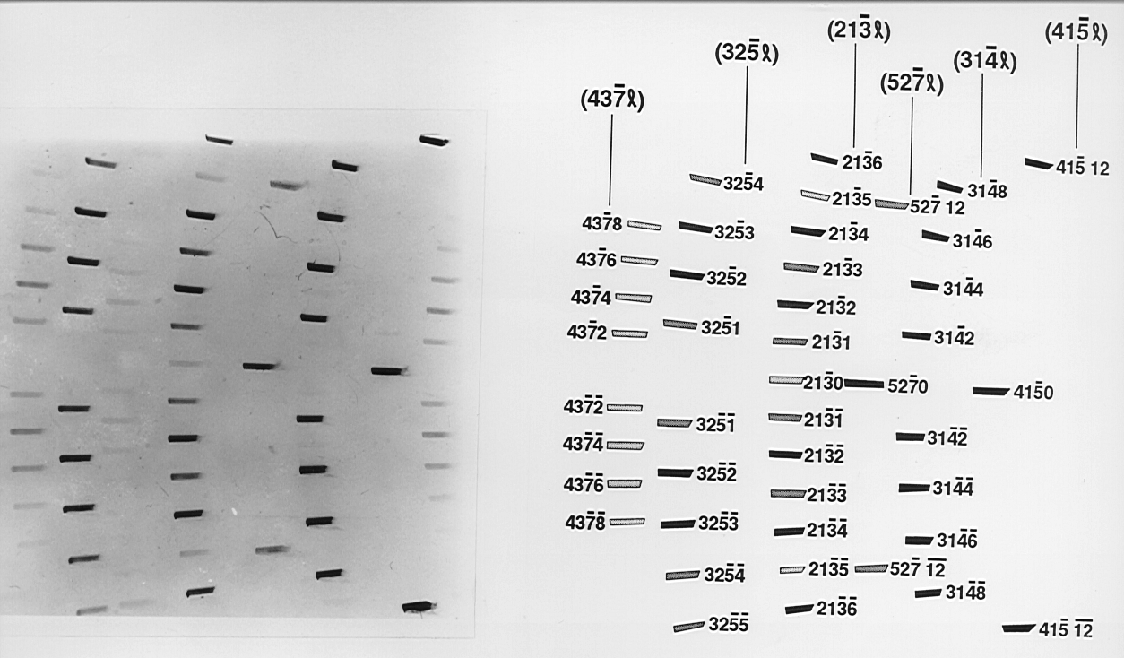
The most commonly found polytype in SiC, 6H is shown in Figure 7, this edge topograph was indexed using the computer programme WRIST (White Radiation Indexing of Synchrotron Topographs) developed by Fisher and Barnes (op. cit). The techniques these authors have pioneered, in particular the use of the edge geometry Fisher and Barnes (1990) [77] have greatly enhanced the ability to locate the position of one-dimensional disorder in SiC.
The SiC crystals in general contain a combination of polytypes in syntactic coalescence, which result in an array of superimposed Laue type reflections from the various polytypes. Since all polytypes are visible in (hk.0) reflections they contain information from the whole crystal.
 |
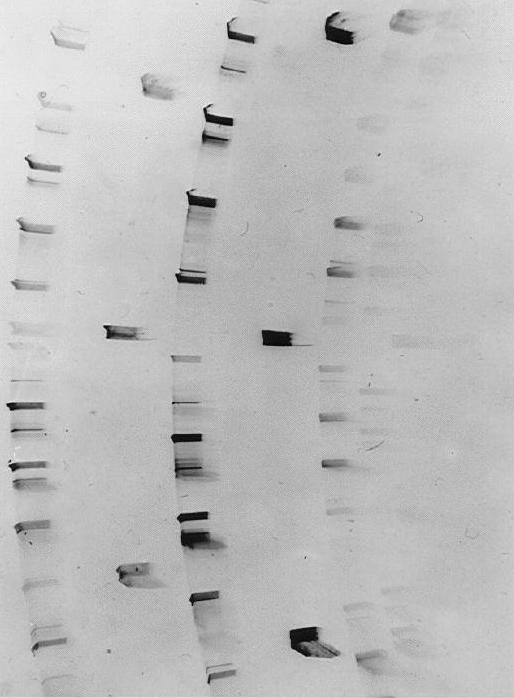 |
| Figure 7. A full plate edge topograph of the 6H polytype in silicon carbide which was indexed using the computer program WRIST (White Radiation Indexing of Synchrotron Topographs) developed by Fisher & Barnes, while the geometry for obtaining such topographs has been described by the same authors op. cit. | Figure 8. A good example of a highly disordered silicon carbide crystal shown by the extensive streaking evident along the diffraction rows. Stacking faults along the crystallographic c-axis and one-dimensional disorder are prevalent features found in SiC crystals. |
By comparing the various reflections with central l = 0 (zero layer line) reflections the contributions from these reflections to the total crystal thickness may be determined. From a measurement of the thickness of the individual polytypes one finds that these do not always add up to the total crystal thickness indicating quite clearly that layer(s) without a crystallographic repeat in the c-direction must also be present, i.e. one dimensional disorder. A good example of this phenomenon is given in Figure 8.
SUMMARY
Although several theories have been put forward to explain the varied characteristics of polytypism it is difficult to understand fully some of the features of it. These include why different types of uni-dimensional order are found (since one-dimensional systems should not normally show long range ordering) an apparent violation of Gibb’s phase rule (owing to the existence of several phases under identical conditions), also the presence of syntactic coalescence in crystals and the varying extent of disorder observed.
REFERENCES
[1] Hoppe P., Amari S., Zinner E., Ireland T., Lewis R.S. (1994) ApJ. 430, 870-890
[2] Clayton D.D. (1997) Astrophysical Journal 484, L67-L70
[3] Timmes F.X. and Clayton D.D. (1996) ApJ. 472, 723-741
[4] Moissan H. (1905) Comptes Rendus Hebdomadaire vol. CXL, 405-406
[5] Moissan H. (1893) C. R. Heb. CXV11, 425-428
[6] Acheson A.G. (1892) English Patent No 17,911
[7] Berzelius J.J. (1824) Ann. Phys. Chemie. Folge 1, 169-230
[8] Lely J.A. (1955) Ber. Deutsch. Keram. Ges. 32, 229-231
[9] Round H.J. (1907) Electrical World (New York) 49, 309
[10] Janzén E., Kordina O., Henry A., Chen W.M., Son N.T., Monemar B., Sörman E., Bergman P., Harris C.I., Yakimova R., Tuominen M., Konstantinov A.O., Hallin C., Hemmingsson C. (1994) Physica Scripta 54, 283-290
[11] Kordina O., Hallin C., Henry A., Bergman J.P., Ivanov I., Ellison A., Son N.T., Janzén E. (1997) Phys. Stat. Sol. (b) 202, 321-334
[12] Glass R.C., Henshall D., Tsvetkov V.F., Carter Jr., C.H. (1997) Phys. Stat. Sol. (b) 202, 149-162
[13] Baumhauer H. (1912) Zeit. Krist. 50, 33-39
[14] Baumhauer H. (1915) Zeit. Krist. 55, 249-259
[15] Schneer C.J. (1955) Acta Cryst. 8, 279-285
[16] Bechstedt F., Käckell P., Zywietz A., Karch K., Adolph B., Tenelson K., Furthmüller J., (1997) Phys. Stat. Sol (b) 202, 35-62
[17] Frank F.C. (1949) Discuss. Faraday Soc. no.5, 48-54
[18] Burton W.K., Cabrera N. and Frank F.C. (1951) Trans. Roy. Soc. A243, 299-358
[19] Mitchell R.S. (1957) Z.Krist. 109, 1-28
[20] Krishna P., Verma A.R. (1965) Z. Krist. 121, 36-54
[21] Pandey D., Krishna P. 1975 (a) J.Cryst. Growth 31, 66-71 (b) Phil. Mag. 31, 1133-1148
[22] Pandey D., Krishna P. (1978) Advances in Crystallography Oxford and IBH, New Delhi
[23] Jagodzinski H.1954 (a) Neues Jb. Miner. Monatsh. 3, 49-65 (b) Acta Crystallogr.7, 300
[24] Verma A.R., Krishna P. (1966) Polymorphism and Polytypism in Crystals J.Wiley, New York
[25] Trigunayat G.C., Chadha G.K. (1971) Phys.Stat. Sol. (a) 4, 9-42
[26] Pandey D., Krishna P. (1983) Prog. Cryst. Growth Charact. 7, 213-257
[27] Schaffer B.T. (1969) Acta. Cryst B25, 477-488
[28] Trigunayat G. C. (1991) Solid State Ionics 48, 3-70
[29] Ramsdell L.S. and Kohn J.A. (1952) Acta. Cryst. 5, 215-224
[30] Knippenburg W.F. (1963) Phillips Res. Rept. 18, 161-274
[31] Hayashi A. (1960) J. Mineral. Soc. Japan 4, 363-371
[32] Loubser J.H.N., De Sousa Balona J.A. and Van Ryneveld W.P. (1969) Mat. Res. Bull. (Proc. Int. Conf. on SiC) 4, S249-S260
[33] Gomes de Mesquita A.H. (1967) J. Appl. Cryst. 23, 610-617
[34] Ott 1925 (a) Zeit. Krist. 61, 515-531 (b) ibid. 62, 201-217
[35] Ramsdell L.S. (1947) Am. Mineral. 32, 64-82
[36] Hägg G. (1943) Arkiv. Kemi. Mineralogi Geologi 16B, 1-6
[37] Zhdanov G.S., Minervina Z.V. (1945) Compt. Rend. Acad. Sci. USSR 48, 182-184
[38] Zhdanov G.S., Minervina Z.V. (1946) J. Phys. USSR 10, 422-424
[39] Jagodzinski H. (1949) Acta Crystallogr. 2, 201-207
[40] Van Haeringen W., Bobbert P.A., Backes W.H. (1997) Phys. Stat. Sol (b) 202, 63-79
[41] Frank F.C. (1951) Philos. Mag. 42, 1014-1021
[42] Amelinckx S. (1951) Nature 167, 939-940
[43] Verma A.R. (1951) ibid. 167, 939
[44] Amelinckx S. (1951) Nature 168, 431
[45] Verma A.R. (1951) ibid. 168, 430-431
[46] Mardix S., Kalman Z.H. and Steinberger I.T. (1968) Acta Crystallogr. A 24, 464-469
[47] Bogdan N. and Alexander B. 1989 (a) Phase Transitions 16/17, 549-553 (b) ibid.
555-559
[48] Ramasesha S. and Rao C.N.R (1977) Phil. Mag. 36 no.4, 827-833
[49] Ramasesha S. (1984) Pramana (India) 23 no.6, 745-749
[50] Kabra V.K. and Pandey D. (1989) Phase Transitions 16/17, 211-229
[51] Farkas-Jahnke M. (1994) Materials Science Forum 150-151, 65-76
[52] Inoue Z. (1982) J. Mat. Sci. 17, 3189-3196
[53] Goodby R., Needs R.J. and Payne M. (1990) Physics World 3 no.10, 39-43
[54] Cheng C., Needs R.J. and Heine V. (1988) J. Phys. C 21,1049-1063
[55] Cheng C., Needs R.J., Heine V. and Jones I.L. (1989) Phase Transitions 16/17, 263-274
[56] Kozielski M.J. and Tomaszewicz A. (1993) Phase Transitions 43 (1-4) unrefereed abstract
[57] Durovic S. (1993) Phase Transitions 43 (1-4), 81-87
[58] Zvyagin B.B. (1988) Comput. Math. Applic. 16, no.5-8, 569-591
[59] Zvyagin B.B. (1993) Phase Transitions 43(1-4), 21-25
[60] Price G.D. and Yeomans J.M. (1984) Acta Crystallogr. B 40, 448-454
[61] Smith J., Yeomans J.and Heine V. (1984) NATO ASI Series E 83, 95-105
[62] Yeomans J.M. and Price G.D. (1986) Bull. Mineral. 109, 3-13
[63] Price G.D. and Yeomans J.M. (1988) Proc. CMS workshop Los Alamos, Springer Verlag, p 60-73
[64] Ising E. (1925) Zeit. f. Physik 31, 253-258
[65] Elliot R.J. (196 ) Phys. Rev. 124, (2), 346-353
[66] Jepps N.W. and Page T.F. (1984) J. Prog. Cryst. Growth Charact. 7, 259-307
[67] Takei W.J. and Francombe M.H. (1967) J. Appl. Phys 18, 1589-1592
[68] Golightly J.P. and Beaudin L.J. (1969) Mat. Res. Bull. (Proc. Int. Conf. on SiC) 4, S119-S128
[69] Fisher G.R. (1986) Ph.D Thesis, University of London
[70] Lang A.R. (1959) Acta Cryst. 12, 249-250
[71] Fisher G.R. and Barnes P. (1984) J. Appl. Cryst. 17, 231-237
[72] Marks N. (1995) Radiat. Phys. Chem. 45, (3), 315-331
[73] Barnes P. and Cernik R. (1992) Physics World 5, (10), 35-40
[74] Barnes P. (1990) Metals and Materials 6, (11), 708-715
[75] Moore M. (1995) Radiat. Phys. Chem. 45, (3), 427-444
[76] Mardix S., Lang A.R., Kowalski G. and Makepeace A.P.W. (1987) Phil. Mag. A 56, 251-261
[77] Fisher G.R. and Barnes P. (1990) Phil. Mag. B61, 217-236
| Back to the filing cabinet |

|