 |
Translational Symmetry
I. Lattices and Unit Cells |
 |
Translational Symmetry
I. Lattices and Unit Cells |
Lattices
So far we have only considered rotational symmetry. This next section takes a look at the translational symmetry which must be present for a crystal to diffract an X-ray beam and produce Bragg reflections.
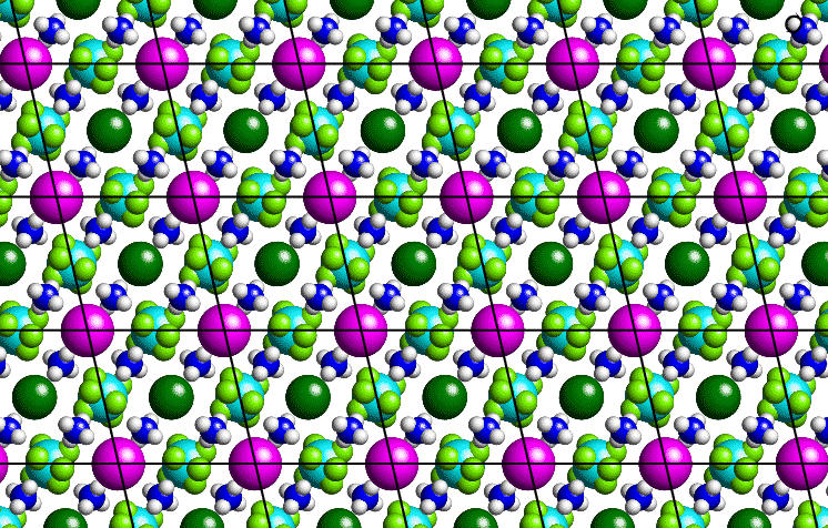
Consider a thin section through a small-molecule crystal structure as shown below: Although the slice is essentially two-dimensional, most of the following arguments apply equally well to a three dimensional system.

The purple-coloured atoms can be joined by straight lines as shown to form a grid or two-dimensional lattice, the basic repeat unit of which is a parallelogram. In order to describe our crystal structure, all we need is a description of the contents of one of these parallelograms plus the symmetry of lattice translation. By repeating the contents of the parallelogram ad infinitum, all of space can be filled. A similar situtation may be observed with commercial wallpaper.
The lattice itself is actually an infinite set of equally-spaced points: It is not the lines which connect the points. (These lines simply provide a useful guide to the eye.) In the real space of a crystal, the origin of the lattice is an arbitrary point chosen by the crystallographer. Thus, an identical lattice would be obtained if, in the above figure, the positions of the dark-green coloured atoms had been chosen as lattice points. (Note the contrast to the reciprocal-space lattice used to identify diffraction spots which has a natural origin corresponding to the straight through X-ray beam.)
Unit Cells
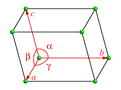
In three-dimensional space, the equivalent repeat unit is a parallelepiped known
as the unit cell as shown below:

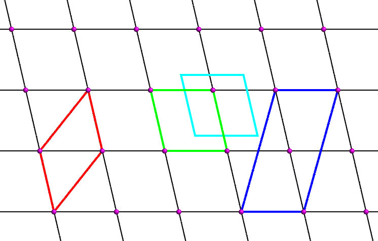
Considering again the "2-dimensional" crystal structure shown above, then the lattice points may be drawn as small purple dots as shown below, based on the purple balls in the figure above:

The question arises as to the choice of parallelogram for our two-dimensional unit cell. The black lattice lines are a result of choosing the unit cell shown in green. However, one could equally choose the unit cells shown in red, cyan or blue. The unit cell shown in cyan is clearly identical to the green one, but has a different choice of origin. Crystallographers usually choose an origin that is convenient to describe the contents of the unit cell. Frequently the origin corresponds to a point of high symmetry within the unit cell: for example, it is often sited on an axis or where two or more axes intersect.
Crystallographers also choose unit cells which contain the smallest number of lattice points. The unit cell shown in blue contains two lattice points (one at the origin corner and one in the middle) whereas the others all contain one. The blue cell is referred to as a centred unit cell; the rest containing only one lattice point are all described as primitive. A primitive unit cell can always be chosen for any two- or three-dimensional lattice, but crystallographers choose centred cells when the centred cell displays the symmetry of the lattice better, e.g. the unit cell may have certain angles constrained to be 90° indicating the presence of an axis (see next page).
Both the red and green unit cells shown above are the same area and have symmetry-equivalent origins. Which is the best choice of unit cell? The red cell has a larger internal angle than the green cell. When the cell angle is not constrained by symmetry, crystallographers usually choose a unit cell such that the cell angles are as close to 90° as possible, and in the above example the green unit cell is the preferred choice.
Centred Lattices
The table below lists the various possibilities for centred unit cells. The multiplicity is the ratio of the volume of the centred unit cell to that of the equivalent primitive one.
| Centring Type | Symbol | Multiplicity |
|---|---|---|
| Primitive - no centring | P | 1 |
| A-face centred | A | 2 |
| B-face centred | B | 2 |
| C-face centred | C | 2 |
| All-face centred | F | 4 |
| Body centred | I | 2 |
| Rhombohedrally centred | R | 3 |
Real-Space Coordinate Systems
It is important to realise that there are two real-space coordinate systems used by crystallographers:
The position of atoms, r, within the unit cell may be given by the vector expression:
These 3-dimensional coordinates, x,y,z, are called fractional coordinates, which range from 0 to 1. These are the coordinates used when dealing with symmetry. The advantage of using fractional cell coordinates for the application of symmetry operators was demonstrated in the section on rotational symmetry.
The fractional coordinates should not be confused with Cartesian X, Y, Z coordinates, which specify the position of the atoms as
where i,j,k are unit vectors in Ångstroms, along orthogonal axes.
|
© Copyright 1995-2006.
Birkbeck College, University of London.
|
Author(s):
Jeremy Karl Cockcroft Huub Driessen |