 |
X-ray absorption, A |
 Course Material Index
 Section Index
 Previous Page
 Next Page
X-ray absorption, A
X-rays are absorbed as they pass through materials according to the exponential
law:
where I0 is the incident intensity, I is the (reduced)
intensity after travelling a distance t through the material and μ
is the absorption coefficient (sometimes also referred to as the photoelectric
absorption (coefficient) due to photo-electron energy losses being the
principal cause). Its value varies with the atomic composition (increasing with
atomic number) and X-ray wavelength (increasing with wavelength); the
wavelength dependence is approximately cubic overall, but with discontinuities
(known as absorption edges) at wavelengths/energies corresponding to specific
electronic transitions within the absorbing atoms.
Sample absorption will obviously affect measured diffraction intensities; we
might first consider the potential scale of the problem. A value often used,
when discussing absorption, is 1/μ since this equals the optimal sample
thickness (i.e. t = 1/μ) for a transmission diffraction experiment:
in fact you can easily show from the above equation that this thickness will
reduce intensities to around 37%. It is quite instructive to look at some
typical values of 1/μ, as in the table below:
|
|
λ=0.56 Å |
λ=1.54 Å |
| perfect vacuum |
∞ |
∞ |
| 10−10 mbar vacuum |
≈1011 km |
≈1010 km |
| helium |
600 m |
300 m |
| air |
15 m |
1 m |
| | | |
| beryllium |
23.5 mm |
3.6 mm |
| aluminium |
1.4 mm |
76 μm |
| lead |
13 μm |
4 μm |
| | | |
| NaCl |
1,110 μm |
61 μm |
| Ca (OH)2 |
840 μm |
48 μm |
Just simply looking at these figures, and remembering that these distances will
cut down intensities to 37%, you should be able to immediately appreciate some
simple practicalities:
- why experiments are sometimes run in vacuum or a helium atmosphere rather
than in air;
- one reason why beryllium is a good material for making X-ray windows;
- why lead is used for cladding X-ray equipment;
- why typical inorganic powder specimens are often made <1mm thick.
In considering the effect of absorption, in the context of powder diffraction,
we can envisage three very different situations:
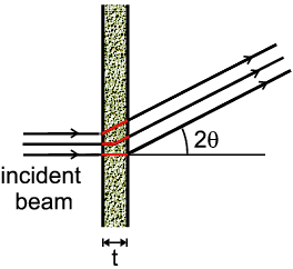
- a powder specimen in the form of a thin plate ("transmission");
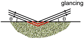
- a powder specimen in the form of a thick plate with Bragg-Brentano geometry
("reflection");
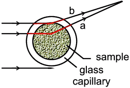
- a powder specimen inside a thin glass capillary ("mixed").
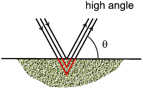
The three situations are depicted below:
| Thin Powder Plate in Transmission |
Thick Powder Plate in Reflection |
 |
 |
| Thin Glass Capillary (mixed) |
|
 |
 |
The resultant effects are quite different. In summary they are:
- Thin plate: The effect is easier to calculate: the absorption
changes with diffraction angle, 2θ, simply because the path length of
X-rays through the sample lie between t and
t/cos 2θ.
- Bragg-Brentano: The effect might not be so obvious how to calculate
but the actual result is so simple: since the incident X-ray beam has a finite
width there will be many paths of different lengths in and out of the sample.
In the example above we see a typical X-ray path for two different angles: at a
low "glancing" (θ) angle, the depth below the sample is small; at higher
angles the same path length requires deeper penetration into the sample.
However the surprising result is that when all the possible path lengths are
taken in to account, the net absorption remains constant with θ. This
means that the effect of absorption can effectively be ignored in this case
since it affects all reflections equally. This is one reason, among others, why
this geometry is often chosen.
- Capillary: The effect is not easy to calculate but the result is
satisfying. As the example above illustrates, some paths appear to be like
transmission (a) and others like reflection (b). There is also the absorption
through the thin glass wall to consider, though this is often negligible by
comparison.
 Course Material Index
 Section Index
 Previous Page
 Next Page


