 |
TOF Diffractometers |
 |
TOF Diffractometers |
Design Concepts
As with angle-dispersive neutron diffractometers, the design of TOF powder diffractometers can be optimized for either high resolution or high intensity or some compromise of both. An understanding of the factors that affect the resolution of the peaks is therefore important. The relative uncertainty in d spacing, δd/d, may be determined from the equation:
where δt, δL, and δθ are the uncertainties in time, path length, and scattering angle, respectively.
From the above equation it may be deduced that high d-spacing resolution may be achieved by (a) using a long flight path, L, which also increases the TOF, t, and (b) by positioning the detectors at high scattering angle, 2θ. The uncertainty in scattering angle is a function of the finite size of the sample and the detector aperture, and can be reduced by increasing the length of the secondary flight path defined as the sample to detector distance. However, an increase in the length of the secondary flight path, gives a sharp decrease in the solid angle seen by the detectors (for a fixed and finite number of detectors), so that in practice the length of the secondary flight path is of the order of 1 to 2 metres and the primary flight path, defined as the pulsed source to sample distance, is designed to be the longer length. One factor that may give rise to an uncertainty in the path length is the finite thickness of neutron detectors: for very high-resolution instruments, thin scintillation counters are generally preferable to the fatter gas-filled detectors. The uncertainty in TOF is largely due to the width of the initial pulse, which is broadened by the passage of the beam through the moderator: thus the thickness of the moderator is a compromise between moderating the wavelength spectrum of the neutron pulse and maintaining its time structure. Finally, given that the detectors are fixed in space, the resolution function, δd/d, for each detector is constant (at least to a first approximation).
The second aspect of the design of TOF diffractometers concerns
the concept of frame overlap and the duty cycle of the instrument.
Consider the case of a 50 Hz pulsed source, where the time between pulses
is 20 ms, and a TOF diffractometer with a
total path length of, say, 25 m. For a neutron with wavelength
1 Å, its TOF will be 6.32 ms
[
TOF Diffractometers
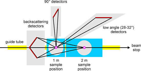
The following generic discussion is loosely based around the high-resolution powder diffractometer HRPD at ISIS, the layout of which is shown schematically below. This instrument has an exceptionally long flight path of about 100 m with detectors at low angle, 90°, and at back scattering as shown. The instrument has two sample positions, but in practice the shorter sample to detector distance is preferred given the greater solid angle for the high angle detectors.

The instrument has three discrete banks of detectors, while modern instruments such as GEM have whole arrays of detectors to completely fill the solid-angle around the sample position. The back-scattering detectors provide data with the highest resolution since cotθ in the angular term in the resolution function is then close to zero.
If the upper and lower limits of the wavelength spectrum are, say, 0.5 Å and 4 Å, respectively, then the range of d spacings measured by a high-angle detector at 160° is 0.254-2.031 Å. Under such conditions the high-angle detectors will not measure the intensities of peaks with d spacings larger than about 2 Å. Under the same conditions, however, the detectors at 90° will simultaneously measure peaks with d spacings up to 2.83 Å, while those at 30° will measure d spacings up 7.7 Å. Thus, the low-angle detectors can be used to measure the larger d spacings, where peak resolution is not so critical given the low density of peaks in this region.
Since the TOF diffractometers have no moving parts, they are preferred over their angle-dispersive equivalents for those experiments that specifically require the use of sample environment equipment with fixed exit windows. This is particularly the case for high-pressure powder neutron diffraction since the pressure cell can be arranged to have windows at 180° and 90° for the incident and scattered beams, respectively. This is an ideal arrangement since, with the careful use of collimation, only neutrons diffracted from the sample are recorded.
| © Copyright 2000-2006. Birkbeck College, University of London. | Author(s): Jeremy Karl Cockcroft |