 |
Instrument X-ray Optics
II. Transmission Geometry |
|
|
Instrument X-ray Optics
II. Transmission Geometry |
Transmission Geometry
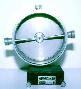 The Debye-Scherrer camera shown in the photograph left used to be
one of the most common instruments for obtaining powder
diffraction data from a sample in transmission geometry.
The camera is discussed here because much of the early
data which formed the JCPDS database (which will be discussed later
in the course) were obtained with this type of instrument.
The Debye-Scherrer camera shown in the photograph left used to be
one of the most common instruments for obtaining powder
diffraction data from a sample in transmission geometry.
The camera is discussed here because much of the early
data which formed the JCPDS database (which will be discussed later
in the course) were obtained with this type of instrument.
The camera was built in a variety of sizes, the most popular having a radius of 180/π (= 57.295) mm. Powder diffraction patterns were collected on film which was wrapped around the inside of the camera in such a way that both the incident beam collimator and through beam collimator both passed through pre-punched holes in the film as shown below. The Bragg scattering angle was readily obtained since the radius was chosen so that 1 mm on the film corresponded to 1° 2θ.
The sample was positioned at the centre of the camera; a shadow of the sample in the X-ray beam could be seen on a small fluorescent screen built into the end of the through beam collimator, and rotated by an external motor attached to the rear of the camera. The cameras were normally used on the spot focus side of the X-ray tube with a cylindrical incident beam collimator; slit collimators were usually available for those occasions when the camera was used with an X-ray line source.
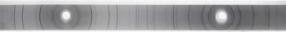
Although the collimators cut down on air scatter, they have little focussing effect. The result is that Debye-Scherrer films measure relatively low-resolution powder diffraction data. However, the semi two-dimensional nature of the strip of film could be used to test for texture in the sample (as discussed later). In addition, the film measured the full 360° of scattering thus providing reasonably accurate lattice parameters from the very high-angle reflections.
The cameras were normally used on a filtered X-ray source and the presence
of the unresolved Kα wavelengths
significantly broadened the peaks at intermediate
2θ angles. At the highest angles, splitting
of the peaks due to the two wavelengths could be seen readily.
Focussing Debye-Scherrer Geometry
The transmission geometry of the Debye-Scherrer camera discussed above can be considerably improved with the introduction of a focussing narrow-band pass monochromator as shown in the diagram below:
The divergent beam from the X-ray anode is focussed using a curved silicon monochromator, not onto the cylindrical sample, but beyond onto the 2θ measuring circle of the detector. As with the equivalent Bragg-Brentano geometry, the angle ξ is optimised at about 6°; and the monochromator Bragg angle is calculated according to the d spacing of, say, (111) silicon. With this geometry, diffraction peak widths of 0.1° or better are easily obtained. An experimental setup for this geometry is illustrated in the photograph below:
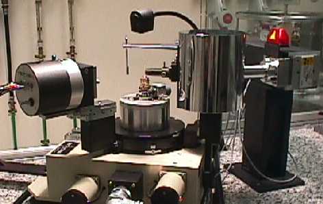
The horizontal X-ray tube is visible far right and a small PSD detector is seen on the far left; the chrome shielding of the monochromator housing dominates the centre right of the picture.
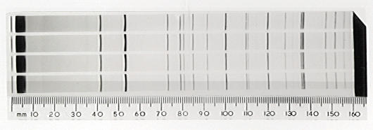
An alternative transmission setup, in which the focussing effect of a monochromator is also exploited, is the Guinier camera. This film-based camera employs thin flat samples in transmission geometry and very high-resolution powder patterns may be measured with it. A typical film from a Guinier camera is shown below for comparison with the Debye-Scherrer film above. However, a detailed usage of this camera will not be discussed further in this course.
| © Copyright 1997-2006. Birkbeck College, University of London. | Author(s): Jeremy Karl Cockcroft |